» » »
Projector Control Modules
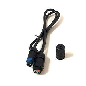
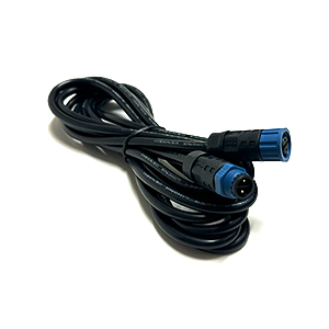
3-Pin Line Power Extension Cable 6ft
Waterproof line power extension cable for ECO Spot projectors with an external driver, PCE-Series, and ECO Lines projectors. This cable extends the line power cord to the driver.
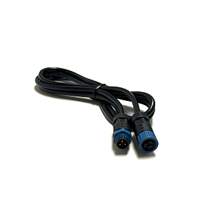
Driver Control Input Extension Cable 6ft
Waterproof extension cable for interior and exterior projectors. This cable connects to the control input connector of external ECO Spot drivers. It is used for dimming or on/off control.
Additionally, it can be used as an extension cable between our CM1 Control Module and its power supply.
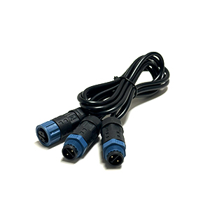
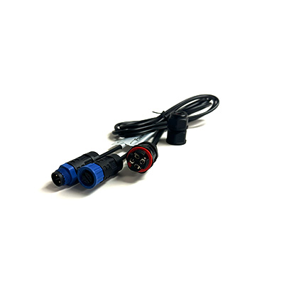
Driver Control Input Y-Cable
Waterproof cable that enables control of two projectors from one control source.
This cable connects to the control input connector of external ECO Spot drivers. It is used for dimming or on/off control. It is especially useful to control two projectors from a single CM1 Control Module.
ECO Spot Driver Control Field Wiring Input Adapter
Adapter that allows for field wiring to the driver control unit. Useful for connecting a control wire without having to cut off the projector’s control input connector.
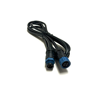
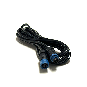
Driver Control Input Extension Cable 12ft
Waterproof extension cable for interior and exterior projectors. This cable connects to the control input connector of external ECO Spot drivers. It is used for dimming or on/off control.
Additionally, it can be used as an extension cable between our CM1 Control Module and its power supply.
ECO Spot Power Insertion Field Wiring I/O Adapter
Adapter that allows for field wiring to the driver control unit. Useful for connecting a control wire without having to cut off the projector’s control input connector.
3-Pin Line Power Extension Cable 12ft
Waterproof line power extension cable for ECO Spot projectors with an external driver, PCE Series, and ECO Lines projectors. This cable extends the line power cord to the driver.
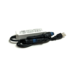
External Mean Well LPF-25-12 Power Supply 12V
Mean Well LPF-25-12 Power Supply for CM1-AB Control Module
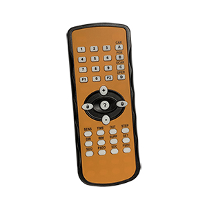
RAVEN/MWave Remote Configuration Tool
The RAVEN/MWave Remote Configuration Tool allows for wireless configuration of the RAVEN/MWave motion sensor.
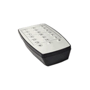
EMX OWL Configuration Tool
The OWL-RC Wireless Remote Control allows for configuration of the OWL motion sensor.
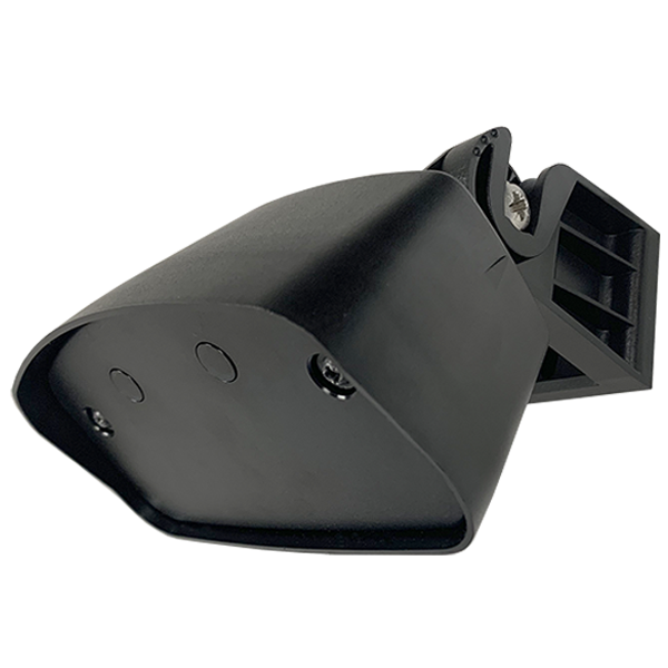
RAVEN/MWave Directional Microwave Motion Sensor
The RAVEN/MWave motion sensor can be used to control virtual sign and line projectors in response to traffic and pedestrians, and can integrate with industrial doors and gates to create dynamic signage for entrances or intersections.
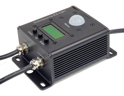
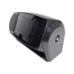
ECO Spot Control Module CM2
The ECO Spot Control Module is an optional module that is designed to add dynamic functionality, such as dimming, blinking, fading, and motion sensing to ECO Spot gobo projectors. The integrated motion sensor (PIR Sensor) can be used in a wide range of modes.
The module connects to a 12 V power supply (included) and to the projectors’ LED driver control inputs. This unit is also capable of passthrough of 12 V power to motion sensors, simplifying installs.
EMX OWL Microwave Motion & Infrared Presence Sensor
The OWL is a motion and presence sensor that utilizes both a microwave and infrared sensor to detect and distinguish between both vehicles and pedestrians. The sensor has two relay outputs, one for vehicle motion detection and one for presence detection. It can be configured to adjust the detection area and relay hold time, as well as filtering options for pedestrians, parallel and departing traffic, as well as weather and particulate noise.